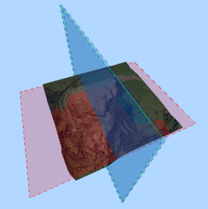
Section Properties
To access this dialog:
-
In the Sheets control bar, active 3D window folder, Sections folder, right-click a section object, select Properties.
-
In the Sheets control bar (Sheet, Projection, 3D Overlay Group sub-menu), double click the Section Line option.
-
In the active 3D window, double-click a section plane.
Note: A Datamine eLearning course is available that covers functions described in this topic. Contact your local Datamine office for more details.
The Section Properties dialog is used to control the section name, orientation, mid point, dimensions, width, plane and extents display properties and clipping parameters (primary and secondary). It is also used to update the section definition used to represent an overlay with a 3D Overlay Group of a plot sheet.
The behavior of this dialog (particularly, the fields that are available for editing) depends on from where the section data was originally derived:
-
If you have imported a section definition file, or one exists in memory, you can see the definitions held within the imported table, but you will not be able to edit them individually - this must be achieved by the parent application. You can view all associated section definitions using this dialog. Section Table-based objects will have the Section Orientation, Section Mid-Point, Plane Dimensions and Section Width options disabled, as these are controlled by the table.
-
If you are using a default section or section created in the 3D window you can access and edit that definition, using this dialog
-
If you are updating the section used to represent a 3D overlay (within a 3D Overlay Group folder) in the Plots window, you can edit the section used within that projection using this dialog. More about 3D Overlay Groups...
Section definitions can either exist in isolation, as a single plane, or can be part of a Section Definition Table - a table containing (potentially) several records, each of which relates to a unique section orientation and position. You can use the active 3D window to define a single-instance definition, but if you wish to make use of a section definition table, it must be created or imported. For more information on creating 3D sections, click here.
You can also edit your section position, dip and azimuth interactively, using Section Widgets.
Field Details:
Name: you can
edit the description in this field to alter the name of the section
object in the active 3D scene. Note that this description is editable
even if the section properties relate to an imported section definition
table. This name is the one displayed in the Sections
folder. Note that editing the name of a
|
|
The default section Name can be changed using this dialog. If the section is dependant on a section definition or view definition table, the table name will automatically be shown in the Section Table field. |
Section Table: this read-only field will show the name of the section definition file that the selected sections object was formed. If the section was created within the active 3D window, this field is blank.
Section Orientation: set the base orientation for the selected section using the Horizontal, North-South and East-West buttons. Note that you can also edit the Azimuth and Inclination of each section individually by manually entering the numeric values for each in the fields to the right of the buttons.
Section Ref Point: manually set the mid point of the selected section in 3D space by defining the requisite X, Y and Z coordinate values. The mid point is the point around which any section rotations occur, and also determines the mid-point of the visible section when Plane Dimensions are being used.
Plane Dimensions:
by default, each defined plane is infinite in both key axes, however,
you can override this setting and define your own section limits by
enabling the Use Dimensions
check box and entering the required values for Width
and Height.
These properties may also be set by an associated view definition table.
To use the limits in the visual display, ensure the Use
dimensions option is selected. If this option is not selected,
the plane is given a default visual representation, where the
centre of the display is in line with the centre of the visible data,
and the width and height is equal to the radius of the data bounding
sphere.
Position: these
up and down arrows allow you to traverse multiple sections within
a section definition file (if the dialog relates to an imported file).
If a section definition file is loaded, these buttons allow you to
move forwards and backwards through the available definitions, displaying
each defined section in turn.
If a new section has been created within the active 3D window,
these buttons will shift the plane backwards or forwards by the designated
Section Width (see above).
Clipping: define how (and if) clipping is to be applied in relation to the defined section. Note that these settings are tied to the selected section only, and do not apply to all section planes in view:
The use of clipping may have an effect on the visibility of data which is drawn (digitized) on the section plane. This can be controlled by the Clipping group options in the Environmental Settings dialog. Also note that you can temporarily disable clipping in any 3D view (independently) using either the View ribbon's Ignore Clipping option, or an external (linked) 3D window's drop-down Clipping menu. Previous clipping values can be reinstated in any window at any time - this is useful for, say, comparing a section view of a block model with an unclipped view of the model, pit and topography in a different viewing window. |
Front: all items in front of the main section plane is clipped.
Back: all item behind the main section plane is clipped.
Outside: all items, except those falling within the defined Section Widths (see above) from the current section plane is clipped out.
Disable on hide: if selected, then data clipping is only performed when a particular section is displayed. When this option is not selected, then any clipping relating to a section is applied, even when its view is disabled. Deleting a section, with or without this option enabled, ensures that any associated clipping is also deleted from the scene.
This option is not enabled for the default section, although it is enabled by default for any sections that you create.
Primary Clipping: the Front and Back settings in this part of the dialog determine the clipping limits of the section for primary clipping, when clipping is enabled (see below). You can set Front and Back directions independently.
If you are defining a section to support the display of 3D window data, you can opt to apply clipping to either the Front or Back of the section independently.
If you are defining a section to support the display of 3D overlays in a 3D Overlay Group of a plot sheet, only None and Outside options are supported.
Even if clipping is not applied, you can show an indication of the section width using the Section Extents properties (further below).
Selecting the Infinite check box will effectively disable primary clipping regardless of other view clipping controls. The Primary Clipping is measured from the section plane forwards or backwards and must be less than the current Secondary Clipping values (as these are also measured from the section plane).
Secondary Clipping:
if secondary clipping is enabled, the data in the clipped region is shown in an unlit grey colour. The size of the secondary clipping
region is, by default, infinite (i.e., all clipped data in the secondary
clipping region is displayed) but can be edited to a fixed value by
disabling the Front and/or
BackInfinite
check box and entering a distance, measured from the section plane,
below which secondary clipping formatting is applied.
Secondary clipping value(s) must be greater than the corresponding
Primary Clipping value(s).
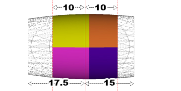
For example, in the image below, an ellipsoid
overlay, 20 meters wide, has been transected by the active section.
Primary Clipping is applied
with both Front and Back clipping distances set to
10m. The Secondary Clipping
is applied to 15m at the Front
(right) of the section and 17.5m at the Back
(left):
More about secondary view clipping...
Section Plane: configure how your section plane is displayed on screen using the property fields in this area:
Fill: flood the section plane with a (by default, semi-transparent) color.
Lines: show the boundary lines of the section as hatched lines.
Arrow: show an arrow indicating the front facing aspect of a section. This is important when differentiating the front and rear of a section plane when clipping is applied according to the Front and Back values set.
Color: set a color for the section plane by double-clicking the color-preview pane. A color picker will then be shown, allowing you to select another color.
Opacity: set the transparency of the section plane here, from 0% to 100% (opaque)
Section Extents: configure how your section plane clipping limits are displayed on screen using the property fields in this area:
Fill: flood the section limit marker with a (by default, semi-transparent) color.
Lines: show the boundary lines of the section limit marker as hatched lines.
Color: set a color for the section limit markers by double-clicking the color-preview pane. A color picker will then be shown, allowing you to select another color.
Opacity: set the transparency of the section limit marker here, from 0% to 100% (opaque)

|
| Related Topics |
| Using
the Sections folder options |

